Industrial 3D Printer Buyers Guide
Over 77% of printers marketed for high performance polymers can’t reliably print PEEK or ULTEM. Make your next investment with confidence, not consequences.

The question isn’t whether ULTEM™ can be printed in a 120°C chamber. It’s whether a 120°C chamber can deliver the parts and properties your application requires.
If the answer is yes, this article could save you more than $100,000. If the answer is no, choosing the wrong printer won’t just cost you money—it might cost months of engineering time spent redesigning parts, tuning print parameters, and chasing repeatable results.
Rather than relying on marketing claims or anecdotal evidence, we decided to test it.
At AON3D, we’ve spent the past decade studying exactly how chamber temperature influences printability, mechanical performance, and process reliability. To quantify those effects, we compared parts printed in a 120°C chamber against identical parts printed at the recommended chamber temperatures:
- ULTEM™ 9085: 185°C chamber
- ULTEM™ 1010: 210°C chamber
Our evaluation focused on the three questions that ultimately determine manufacturing capability:
- Can my parts be printed reliably?
- Do they achieve the expected mechanical performance?
- Can those results be repeated across printers, production runs, and different parts?
Printability Test: Can You Actually Produce the Part?
Successfully extruding a polymer is only the beginning. Whether a part remains attached to the build plate, warps, cracks, or develops strong interlayer welds is determined by how the polymer cools after deposition. Those thermal conditions become increasingly difficult to maintain in colder build chambers.
For both tests, a 120°C chamber and 185°C bed were used, in order to closely mirror several low-cost “high temperature” 3D printers.
Geometry #1 — To evaluate printability, we intentionally avoided highly optimized benchmark parts. Instead, we started with a simple, fully dense rectangular specimen—no unsupported overhangs, no complex toolpaths, and no intricate geometry.
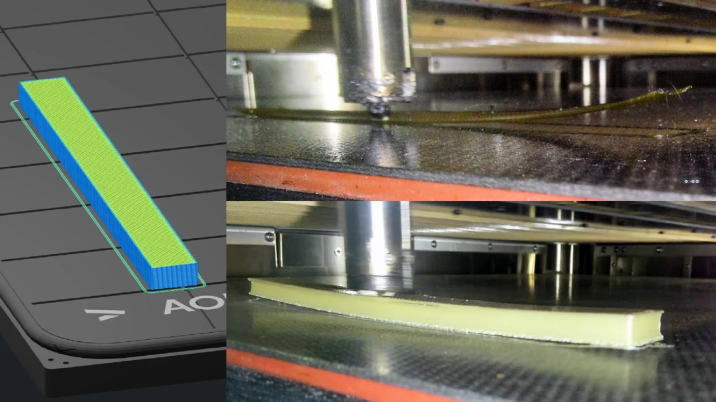
Even this simple part could not be completed in a 120°C chamber. Every attempt warped off the build plate within the first few layers. We eventually rounded the corners and applied an adhesion aid simply to improve first-layer survival, yet failures remained common.
Geometry #2 — To test how geometry influences printability, we selected a pulley with a circular profile. Unlike square or sharp corners, circular features distribute shrink forces uniformly around the circumference, preventing stress from accumulating at any single location.
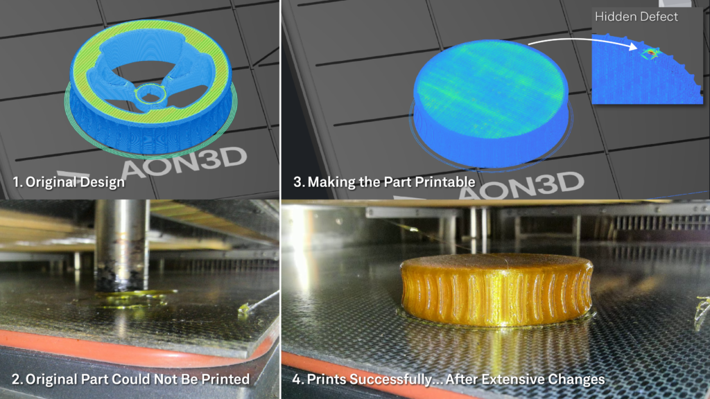
To successfully manufacture geometry #2 at 120°C, we were forced to:
- Simplify the geometry by removing the internal spokes
- Switch to concentric bottom layers
- Reduce infill
- Start the print at the recommended chamber temperature before lowering the chamber to 120°C
Only after modifying both the design and the manufacturing process could the part be printed successfully.
Key takeaway
Printing ULTEM in a 120°C chamber will require process modifications, geometry modifications, and lots of trial-and-error printing on a per-part basis. Every new part or design modification becomes a process development exercise.
Mechanical Testing: Are You Getting ULTEM Performance?
Producing a successful print is only half the challenge. The more important question is whether those parts still deliver the mechanical properties engineers expect from ULTEM™.
To answer that question, we printed ASTM D638 Type I tensile specimens in the ZX orientation, simultaneously printing five coupons at a time to replicate the thermal conditions experienced by real parts when printed. We also tested a non-standard chain-link geometry to determine whether the same trends extended beyond standardized test coupons.
We selected the ZX orientation because it provides one of the most demanding evaluations of process quality. In this orientation, the applied load must be transferred across hundreds of deposited layers, making failure highly dependent on the quality of the interlayer welds formed during printing.
Producing usable 120°C specimens required a hot-chamber-start/cold-print process, adhesion aids, and multiple failed print attempts before sufficient specimens could be produced for testing.
ULTEM™ 9085 Results
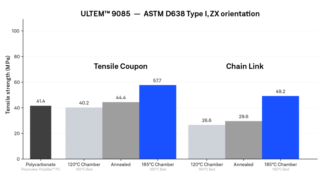
Printing ULTEM™ 9085 at its recommended 185°C chamber temperature increased ZX tensile strength by approximately 44% compared with parts printed at 120°C.
Equally important, specimens printed at the higher chamber temperature improved ductility and demonstrated substantially better consistency between samples, indicating a more repeatable manufacturing process.
Although 40 MPa may appear respectable, it represents a significant departure from the performance engineers purchase ULTEM™ 9085 to achieve. At approximately $220/kg, the cold-printed specimens exhibited ZX tensile strength comparable to desktop polycarbonate printed on low-cost systems.
ULTEM™ 1010 Results
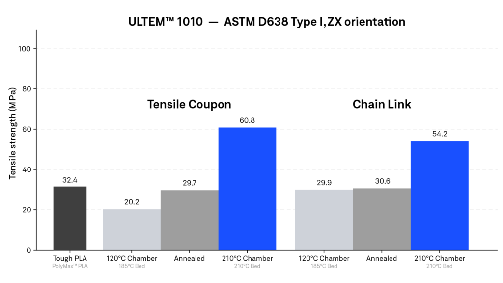
The performance difference became even more dramatic with ULTEM™ 1010. Printing at the recommended 210°C chamber temperature increased ZX tensile strength from 20.2 MPa to 60.8 MPa—an improvement of more than 200%.
Perhaps the most striking result is where the cold-printed parts landed. At 20.2 MPa, their ZX tensile strength was comparable to tough PLA printed on a desktop printer.
For a polymer costing roughly seven times more than PLA, engineers are paying a premium price only to achieve commodity-level mechanical performance.
Key takeaway
Simply printing a high-performance polymer doesn’t guarantee high-performance parts. Chamber temperature ultimately determines whether the final component delivers the mechanical properties engineers are paying for.
Can You Design Around a 120°C Chamber?
Yes—but only to a point. Successfully printing in a 120°C chamber often requires designing around the limitations of the manufacturing process rather than the requirements of the application. Understanding those limitations begins with two fundamental concepts…
Keeping Layers Warm Enough, for Long Enough
Chamber temperature determines how long deposited layers remain hot enough to form strong interlayer welds while delaying thermal contraction. Each polymer has a specific temperature at which optimal layer welding can occur:
- Amorphous polymers (ULTEM) – Just below the polymer’s glass transition temperature (Tg)
- Semi-crystalline polymers – Near the polymer’s melting temperature (Tm)
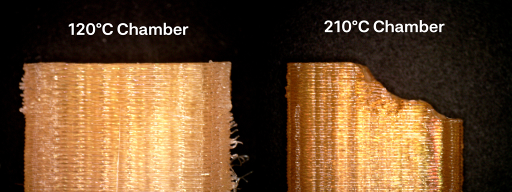
The further below these temperatures you go, the faster polymer chains ‘freeze’, inhibiting their ability to diffuse across layers, resulting in weak interlayer welding. This phenomenon can be seen directly in our test results, where the 90°C delta between 120°C and 210°C yielded a 200% difference in weld strength. For polymers like PEEK, which requires a 240°C+ chamber, you could expect to see even more of a dramatic loss in weld strength.
Managing Thermal Shrinkage
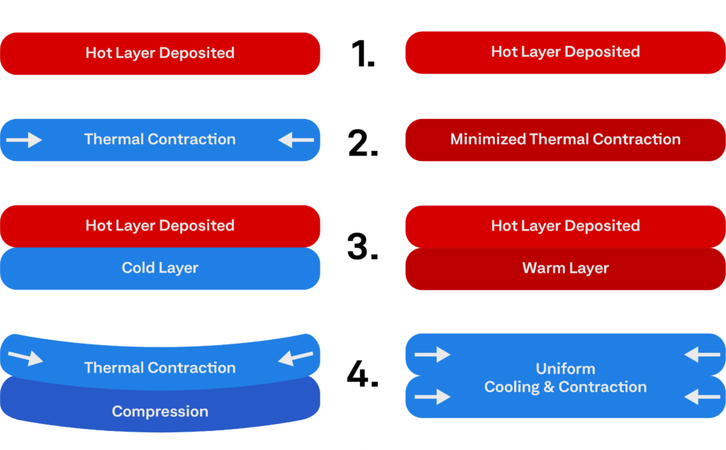
When a polymer is heated in the nozzle, thermal expansion occurs. Upon deposition, the polymer naturally contracts along the deposited toolpath as it cools. A heated chamber doesn’t stop this shrinkage—it delays it. In a cold chamber, each deposited bead begins shrinking almost immediately. Because it is bonded to the previous layer, that contraction is restrained, causing residual stresses to accumulate with every successive layer. When those stresses become great enough, the part warps or, if the interlayer welds are weaker than the accumulated shrinkage forces, the layers separate, resulting in cracking.
So, can you just design around the problem?
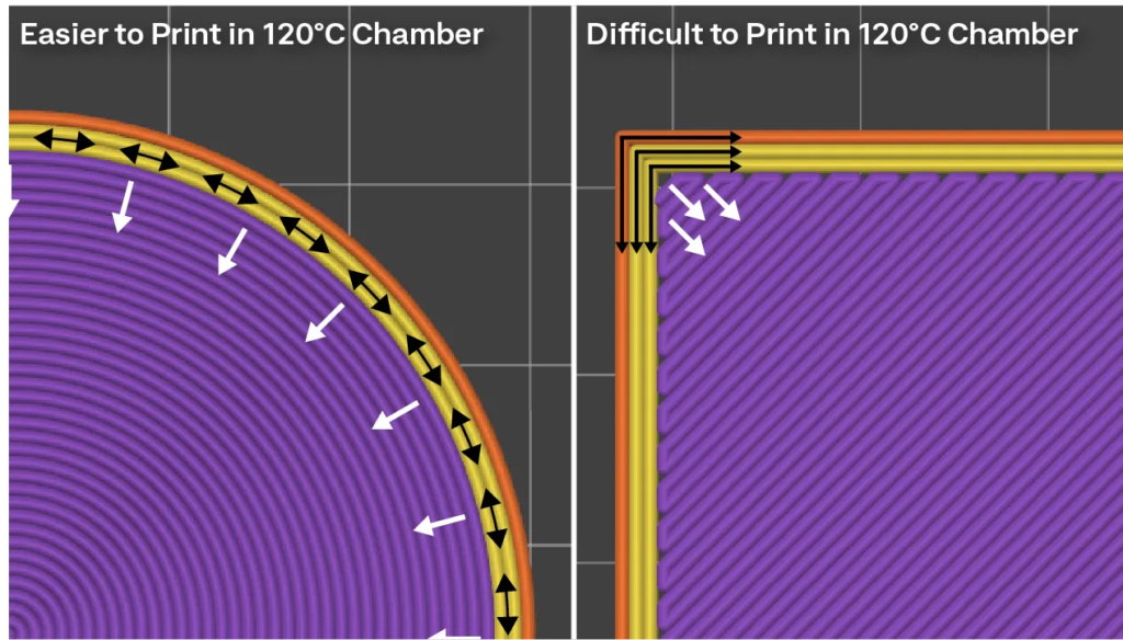
To a degree. Geometry has a significant influence on whether a part can be successfully manufactured in a 120°C chamber. While every printed part shrinks as it cools, rounded features distribute shrinkage forces over a larger area, whereas sharp corners concentrate them at a single location. As residual stresses accumulate during the build, these stress concentrations become the initiation points for warping and interlayer cracking. There is a laundry list of design and slicing tricks that can help, but the process is going to require a lot of trial-and-error tuning for each unique part and design modification.
Repeatability: Every Part Becomes a Process Development Exercise
In a 120°C chamber, every unique geometry and design modification affects how long deposited layers remain warm and how thermal shrinkage forces are distributed.
Successfully manufacturing a part becomes a balancing act. Every design or process adjustment involves tradeoffs. Changes intended to improve interlayer welding can increase residual stress, while modifications that reduce warping often affect layer time, geometry, or throughput. At 120°C, there is very little margin for error.
As a result, process settings that work for one part may fail completely on the next. Every new geometry becomes an exercise in balancing thermal history, shrinkage forces, and process parameters to remain within the printer’s narrow processing window.
A properly heated chamber doesn’t completely eliminate these variables, but it dramatically widens the processing window. By keeping deposited layers hot longer and delaying shrinkage until the build is complete, the process becomes far more tolerant of different geometries and design changes, reducing the need for continual optimization.
If your application consists of relatively small, thin-walled, or rounded geometries, and you’re willing to invest the time optimizing each new part, a 120°C chamber may be sufficient.
For manufacturers producing complex, highly loaded, or frequently evolving parts, however, the question becomes less about whether a material can be printed and more about whether the manufacturing process can keep pace with the application.
Why We Built Hylo
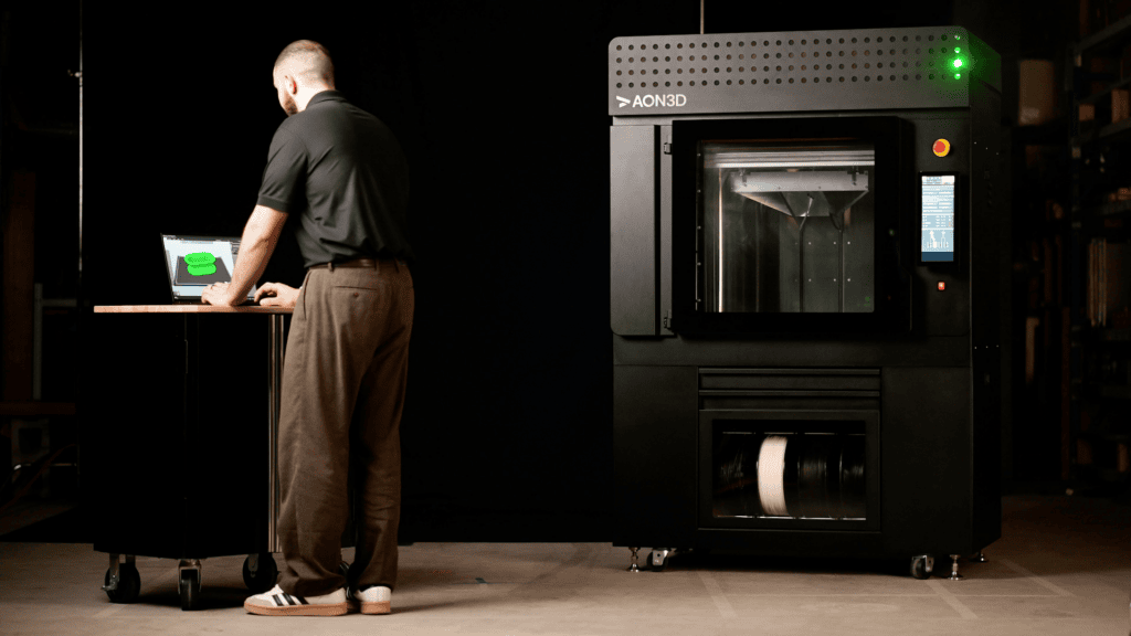
None of these conclusions are theoretical. They were learned through more than a decade of building, testing, and manufacturing high temperature 3D printers.
AON3D introduced its first high-temperature 3D printer in 2015 with a 70°C heated chamber. At the time, our maximum chamber temperature was limited by our ability to reliably cool printer components inside the chamber—a requirement to get around design patents at the time.
Over the following decade, we experienced firsthand which materials, geometries, and process conditions remained manufacturable—and which required extensive compromises.
Those lessons became the foundation for AON3D Hylo.
Rather than expecting engineers to redesign parts, manually tune slicing parameters, and develop unique print processes for every application, Hylo was engineered to expand the manufacturing window itself.
A 250°C actively heated chamber, Multiphysics process tuning, self-calibration, and end-to-end automation all exist for one reason—so engineers can spend their time designing for the application—not the printer.
Achieve New Levels of Part Performance & Throughput
3D print the world's highest performance polymers - bigger, faster, and stronger than ever.