Industrial 3D Printer Buyers Guide
Over 77% of printers marketed for high performance polymers can’t reliably print PEEK or ULTEM. Make your next investment with confidence, not consequences.
In mechanical engineering, when two parts need to fit together, an engineering fit is used — a systematic classification that defines the allowed dimensional variation between mating components. ISO 286 outlines these classes of fits and provides rules for how much size variation (tolerance) is acceptable for holes and shafts.
Unfortunately, ISO 286 was developed for subtractive manufacturing processes such as CNC machining, where extremely tight tolerances can be achieved. The standard is mostly irrelevant for FDM 3D printing due to the greater dimensional variability and surface roughness inherent to the material extrusion process.
Engineering Fit Classifications
Engineering fits are divided into three main categories, each having subcategories that define a range of dimensional tolerances — from running fits with large clearances and lateral play, up to force fits, where heat and substantial force are required to assemble parts that cannot be disassembled without damaging the part.
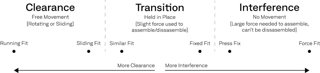
- Clearance Fit: The hole is larger than the shaft, allowing for parts to slide and/or rotate when assembled.
- Transition Fit: The hole is slightly smaller than the shaft, requiring light force to assemble or disassemble.
- Interference Fit: The hole is smaller than the shaft, requiring significant force or heat to assemble.
This guide provides a new set of rules for tolerancing with 3D printed parts, in addition to providing workarounds, compensating for inherent variability, to achieve tolerance and interference fits without excessive testing and tuning.
Clearance Fits
To achieve a reliable clearance fit for FDM parts, start by obtaining your extrusion width — a material-specific parameter found in your slicer’s print settings, typically set to 1.0–1.25X the nozzle diameter*. Since the extruded filament bead tends to bulge slightly beyond its theoretical path, a general rule is to allow a clearance of 1–2× your extrusion width to ensure smooth motion and compensate for variation in bead width and surface texture.
For example, if using a 0.6 mm nozzle with a 0.75 mm extrusion width, design for approximately 0.75 mm clearance between mating parts for a tighter sliding fit, and 1.5 mm clearance for a running fit with free movement.
Keep in mind that this guideline may need adjustment depending on material shrinkage and part size. Semi-crystalline polymers such as PA, PPS, and PEEK generally have higher shrink rates due to polymer chain alignment and crystallite formation, which can cause contraction. Larger components will also require scaled tolerances to compensate for thermal contraction and residual stress warping common in FDM printing.
*If your slicer does not provide explicit extrusion width settings, slice a random model in your target profile. Save and open the resulting GCODE file in a notepad. Near the beginning of the file, you should find “Extrusion Width” settings with explicit values in millimeters. Disregard any top and/or bottom layer extrusion width settings, as they are often different from 99% of your print.
Transition & Interference Fits
In practice, a transition fit represents the tightest dimensional tolerance achievable with FDM 3D printers. However, reaching this fit consistently requires extensive calibration, test coupons, and tuning to establish your printer/material’s dimensional accuracy and scaling factors. Even with careful tuning, process variability can still lead to inconsistent results.
If you need a transition or interference fit with material extrusion parts, consider using design features that create the same mechanical effect without over-stressing the material.
Use Hexagons or Squares Instead of Holes
As shown in the image below, circular holes can only expand by stretching along their circumference, which often leads to material cracking or delamination, especially with high interference. Instead, square or hexagonal geometries reduce the amount of stretching needed — a common FDM design trick for achieving reliable press-fit 3D printed assemblies.
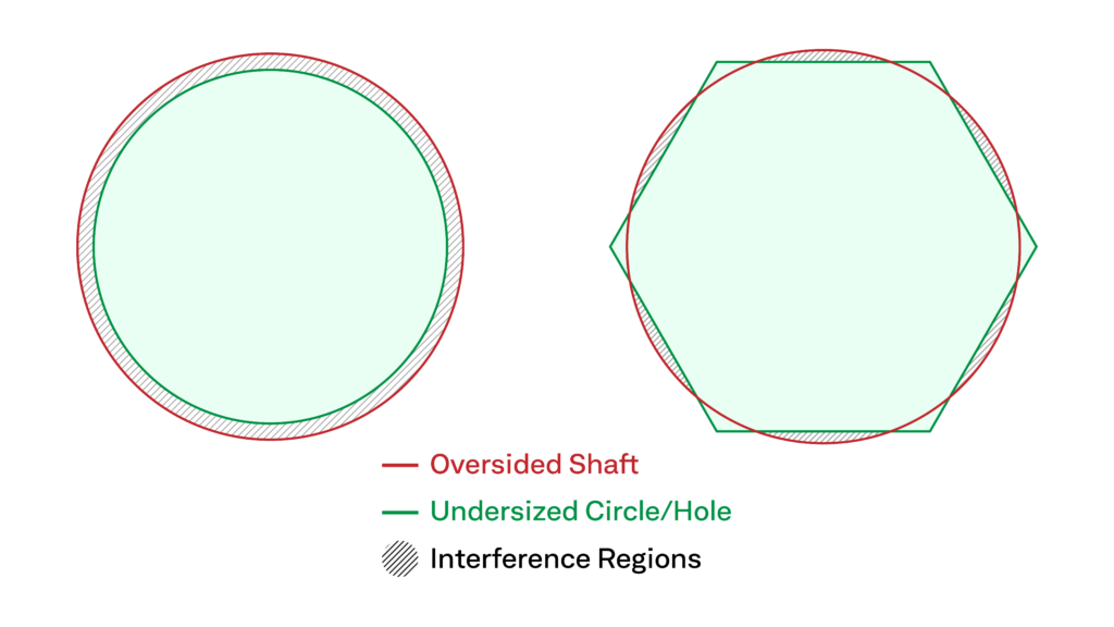
An added benefit to using hexagonal shafts is that Z-seams can be hidden within a corner of the shaft, limiting the dimensional issues and interference caused by the Z-seam.
Crush Ribs
Another method to achieve a functional interference fit in FDM printing, without risking part failure, is to design a clearance fit with integrated crush ribs. These small features deform locally during assembly, providing controlled interference while minimizing stress on the surrounding geometry.
Two approaches are common:
- Transition-Fit Crush Ribs: Slope the inner or outer diameter by ~2°, creating slight clearance on one end, and add 0.2 mm vertical crush ribs around the circumference to compensate (see Dan Royer’s video example).
- Press-Fit Crush Ribs: Add 0.2 mm vertical crush ribs along the full shaft or hole length without tapering. This version creates a true press-fit but should only be used for one-time assembly, as repeated use reduces interference.
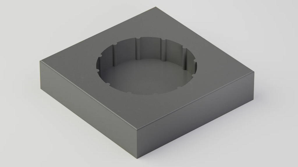
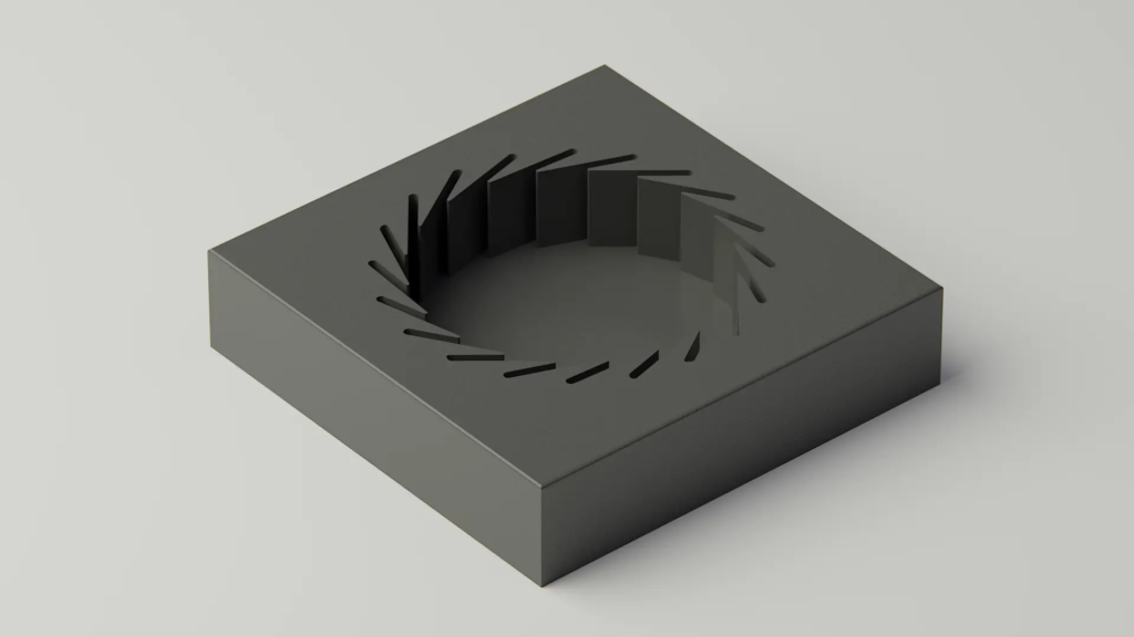
Relief Features
For strong but serviceable connections, adding relief features allows partial expansion of the hole walls during insertion. To add relief features, model the hole at the true shaft diameter, then add thin radial cuts or split sections (see examples below) so the walls can flex during assembly. This technique provides a secure hold with moderate force while allowing reassembly without permanent deformation — ideal for snap-fit or friction-fit 3D printed parts.
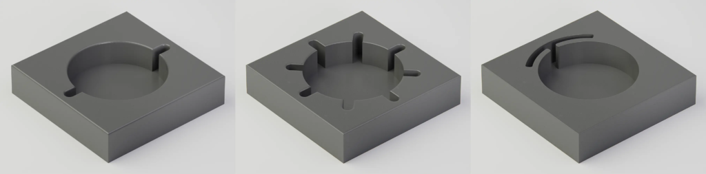
Grip Fins
Grip fins offer a durable transition-fit solution that maintains clamping force over multiple assembly cycles, unlike crush ribs which are one-time use. When designing grip-fin features for FDM, ensure fins exceed your minimum printable feature size (based on nozzle diameter and extrusion width). Trim the base layer of each fin slightly to separate it from the hole floor to allow free movement of the fins.
For small holes capable of bridging, orient the hole opening downward so fins print cleanly.
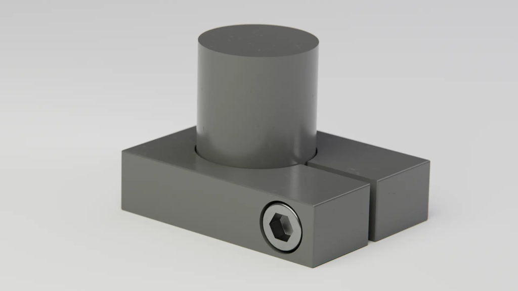
Split Clamps
For geometries where the outer walls of the female component are accessible, split clamps combined with socket head cap screws and embedded nuts can deliver high clamping force while enabling full disassembly. Pay attention to print orientation — overtightening along unfavorable layer line directions can cause layer separation or cracking. Proper orientation and anisotropy-aware design are key to creating durable split clamp mechanical assemblies.
Even with smart design techniques, tolerancing in additive manufacturing still demands constant adjustment to account for material behavior and process nuances. The most reliable way to achieve consistent, production-grade assemblies is to reduce that variation at its source—AON3D’s Hylo™ Industrial 3D Printer leverages end-to-end automation to minimize operator-driven variability, making it easy to manufacture full-scale tooling and end-use parts in the world’s highest performance polymers. Paired with AON3D Basis™ software, which optimizes print settings on a per-part basis, millimeter by millimeter, the platform enables engineers avoid material markups while printing open market materials with the predictability of closed ecosystems—without the price tag.
Achieve New Levels of Part Performance & Throughput
3D print the world's highest performance polymers - bigger, faster, and stronger than ever.