3D Printing with PEEK, PEKK, & ULTEM™
Join AON3D's 3D printing application and materials experts for a 30-minute session that covers all the key information
Additive manufacturing has been celebrated as a revolution in manufacturing technologies, with applications ranging from low-cost prototypes to high performance end-use parts. But the merits of 3D printing aren’t without their own unique processing challenges. The thermal conditions during printing have a profound effect on the final properties of the part, giving rise to undesirable phenomenon such as warping, residual stress, and poor interlayer weld strength. Here, we answer your questions as to why parts shrink during printing, why residual stress occurs and how we can improve layer weld strength in 3D printing.
Why do parts shrink during 3D printing?
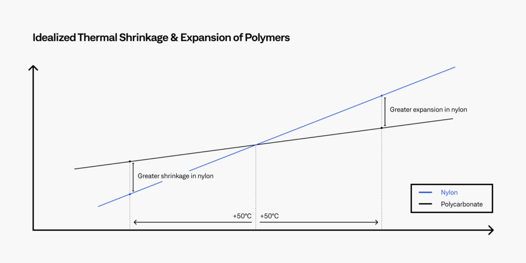
The fused filament fabrication (FFF) process relies on the rapid melting and cooling of plastic filament to consolidate the designed geometry. Like most materials, polymers expand when exposed to heat and the degree of expansion is an intrinsic material property known as the coefficient of thermal expansion (CTE). If you increased the temperature of Polycarbonate and Nylon by 50°C, you would observe greater expansion in Nylon due to its higher CTE. Now conversely, if polycarbonate and nylon are cooled down by 50°C, you will see greater shrinkage in Nylon compared to Polycarbonate as shown in the figure below.
We can see that some degree of shrinkage is unavoidable since polymers need to cool from the extrusion temperature to room temperature. This effect is more pronounced for polymers such as PEEK, PEKK and ULTEM™. When these polymers cool below their glass transition temperatures, they increase in rigidity. Because these parts are stiffer, thermal contractions are inhibited which results in residual stress. The next section will discuss this issue in detail.
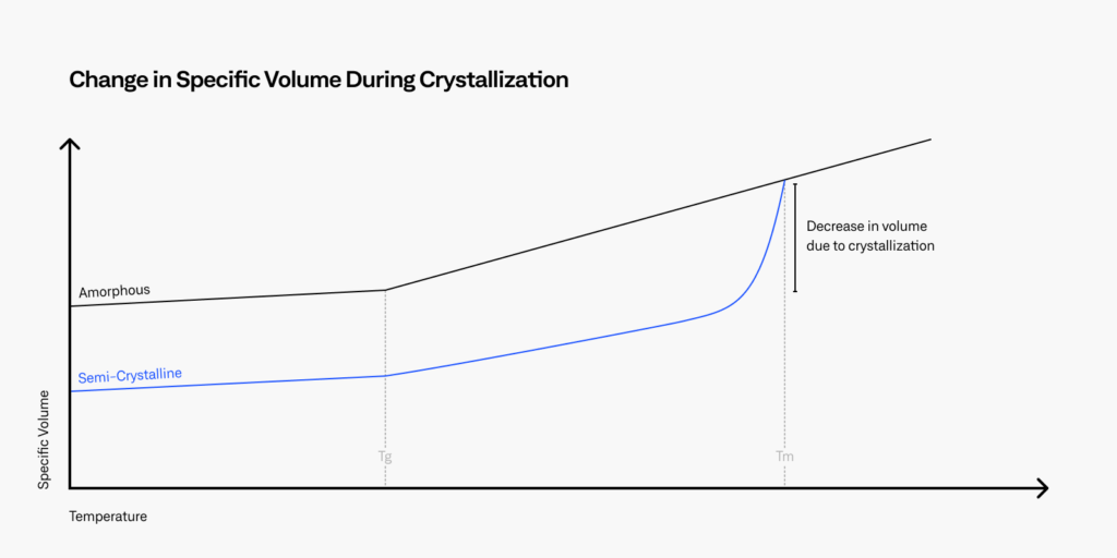
Shrinkage in additive manufacturing can also occur due to crystallization in semi-crystalline polymers such as PLA, Nylon, PEEK and PEKK. As explained in the previous article on the crystallinity of PEEK, semi-crystalline polymers develop crystalline phases during the FFF process. This occurs when polymers are extruded and cooled below their melting temperatures as shown in the figure below. When these crystals form, the volume of the polymer decreases. Shrinkage occurs when these crystalline regions form and generate further residual stress in the part.
But what exactly is residual stress and how does it affect the performance of printed parts? In the following sections we explore how residual stress occurs during 3D printing and provide guidelines on how to reduce it.

What is residual stress and why does it occur?
Heat is brought into 3D printed parts continuously from the top surface due to the layer-by-layer process. Layers below the newly deposited track will cool relative to the extrusion temperature and heat will transfer from the top layer in three ways:
- Conductive heat transfer to the cooled layers below.
- Convective heat transfer to the air around the part.
- Radiative heat transfer to the rest of the part and build chamber.
As heat is lost rapidly from the top layer, the layer begins to shrink. But since the top layer is constrained by the previous layers beneath, the layer is not able to shrink or deform completely. Residual stress is created when a material has the propensity to shrink but is physically restricted.
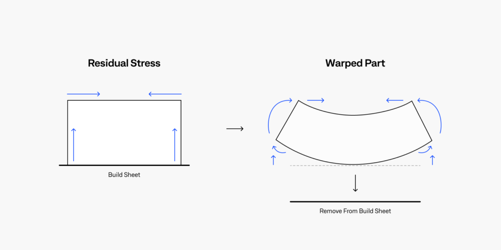
Now if you were to remove this part from the build plate, you will immediately notice that the edges curl. This happens because the part is no longer constrained to the build plate and is free to deform, relaxing the residual stress. Higher residual stress equals greater warping in printed parts as well as poor interlayer strength. Before we suggest improvements for dimensional accuracy and mechanical properties of printed parts, lets first understand why poor layer weld strength occurs in 3D printing.
What causes poor layer weld strength?
If you’re familiar with 3D printing, you may have heard that FFF 3D printed parts are weakest along the z-direction. The way parts are sliced, and the hardware used to print the part both have a considerable effect on the z-axis properties. Here we look at why poor layer weld strength occurs and how we can improve properties to match injection molded polymers.
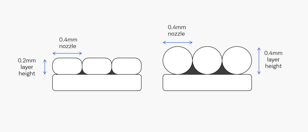
The mechanical properties of all polymers, whether amorphous or semi-crystalline, are affected by the selected layer height when slicing the model. The example below shows tracks printed with a 0.2mm and a 0.4mm layer height with a 0.4mm nozzle diameter. When the chosen layer height is smaller than the nozzle diameter, the deposited bead is squished. This allows the polymer to spread, creating a larger surface area for the printed layers to bond. A larger surface area allows for more polymer chains to interact between layers, increasing the interlayer weld strength. In addition, the squished beads are more rectangular in shape which decreases the pore size between deposited tracks. Pores are detrimental to the mechanical properties of printed polymers since they are sites where delamination failure begins. The extrusion width setting on slicers should also be modified to ensure these pore sizes are minimized.
To further increase the interlayer weld strength, the right hardware is required. When a part is created in layers, the polymer chains on the surface of each layer are initially disconnected. To promote interaction between layers, heat is required to mobilize the polymer chains. Fortunately, the 3D printing process delivers heat as a new layer is deposited. Heat is transferred to the previous layers which improves polymer chain migration and interpenetration. Here the chosen extrusion speed and width play an important role; tuning the speed to ensure enough heat is transferred and the extrusion width to minimize pores is essential. But often, especially for high performance polymers like PEEK, PEKK, and ULTEM, relying on the heat from extrusion is not enough. Therefore, a heated build volume is required to promote the movement of polymer chains between layers and to maximize the mechanical properties of parts in the vertical axis.
How to reduce warping, residual stress and poor layer welding?
The key is to establish a uniform temperature distribution during the printing process. Since all three of these phenomena and thermally induced, lower variations in temperature across the part will decrease warping and residual stress. To minimize warping and ensure properties are maximized for high performance polymers, a heated build chamber is required. Heated build chambers that can exceed 120°C are optimum for maximizing properties on high temperature thermoplastics. Printers such as the AON M2+ allow homogenous temperature distribution within the build volume and will allow layers to stay warm enough for polymer chain migration to increase the layer weld strength. In addition, carefully engineered convective air circulation ensures that thermal stability is maintained and distributed across the volume of the part to prevent warping and localized residual stress.
Achieve New Levels of Part Performance & Throughput
3D print the world's highest performance polymers - bigger, faster, and stronger than ever.