Industrial 3D Printer Buyers Guide
Over 77% of printers marketed for high performance polymers can’t reliably print PEEK or ULTEM. Make your next investment with confidence, not consequences.
Part 1 of this DFAM guide focused on engineering fits for 3D printed assemblies—how to design reliable clearance, transition, and interference fits with additive’s inherently variability. In Part 2, we shift from assembly function to structural performance: how to design and print parts that are stronger, stiffer, and more repeatable under real loading. The guidance in this section treats slicer settings and material choice as part of the design equation—because print orientation, shell/infill strategy, porosity control, and thermal conditions directly determine whether a part merely looks correct or performs predictably.
Add Fillets or Chamfers to Inside Corners
When a load passes through a part, the forces follow paths through the material. Sharp inside corners abruptly disrupt these paths, forcing stresses to concentrate at a single point and increasing the risk of crack initiation. Add a chamfer or fillet where walls meet the base of a part to smooth the transition for load paths, allowing forces to flow gradually from vertical to horizontal sections. This reduces stress concentrations at the wall–base junction, keeps stresses aligned with stronger print directions, and minimizes weak points caused by sudden changes in extrusion path geometry.
Print Orientation
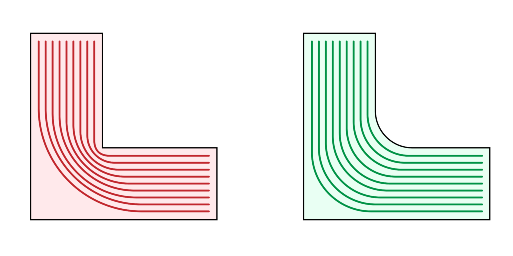
It is well known that material extrusion parts are weakest along the layer lines, so choosing a proper printing orientation is one of the most basic steps to increasing part strength. Before you begin designing, you should consider the direction of load forces. Load forces should be aligned parallel to the print surface.
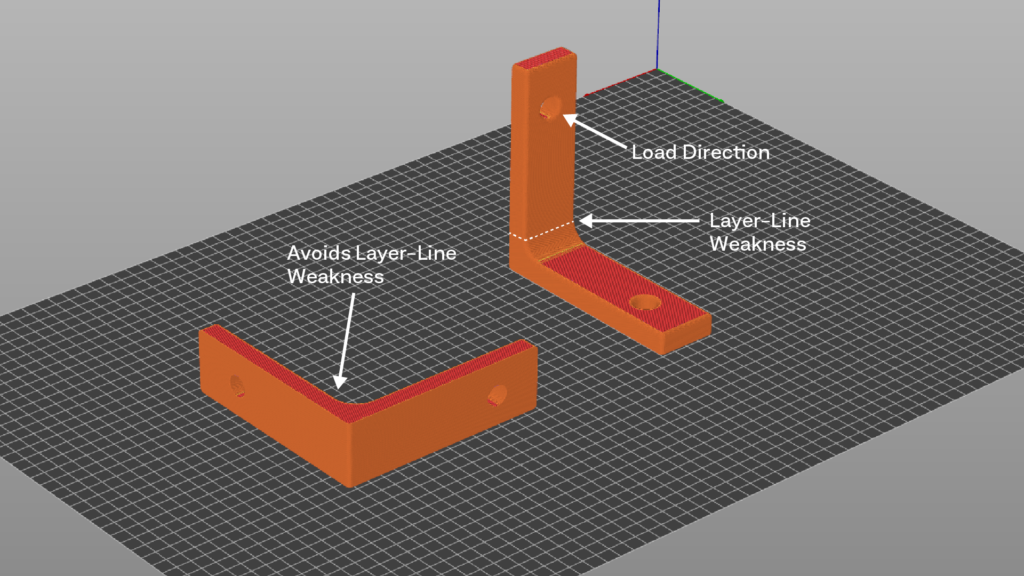
In many cases, parts are subjected to multi-direction loading, and no single print orientation will provide optimal layer line alignment for all critical features. In these situations, you may consider splitting your design into multiple components, each printed in an orientation that maximizes strength where it is needed. Once printed, components can then be joined using methods such as designed-in dovetail joints, bolted connections, or other precision-fit mechanical fasteners.
Perimeters vs. Infill: Matching Material Placement to Load Type
Increasing infill density generally improves tensile strength and elastic stiffness by adding load-bearing material across the entire cross-section. However, for parts primarily loaded in bending, much of this interior material contributes relatively little to flexural stiffness or flexural strength, while significantly increasing print time and part mass.
For bending-dominated parts such as beams, brackets, and cantilevered features, increasing the number of perimeters and top/bottom layers is often more efficient than increasing infill density alone. This approach places material farther from the neutral axis—where tensile and compressive stresses are highest during bending—while achieving higher flexural performance with less material and shorter print times.
General guidance:
- Use higher infill density to improve tensile strength and elastic modulus
- Use additional perimeters to improve flexural stiffness and bending strength
- Balance both for parts experiencing mixed loading conditions
Design decisions should be driven by the dominant load case and production constraints, rather than a single “maximum strength” setting.
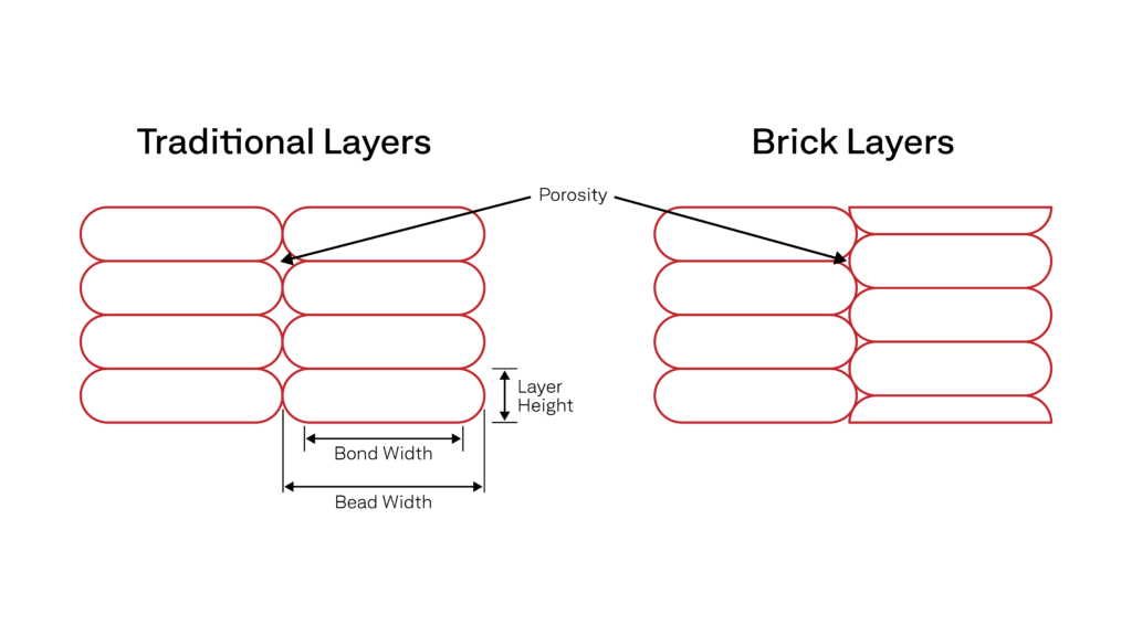
Reducing Porosity: Tuning Your Extrusion Multiplier
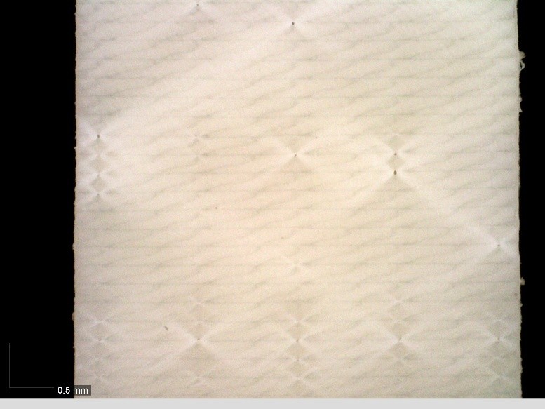
Achieving a fully dense part is one of three core methods to maximize printed part isotropy. There are two main methods to reduce porosity, increasing the amount of ‘squish’ for each deposited bead and/or vertically staggering layers, as seen in the illustration to the right.
To increase the amount of squish, you’ll want to increase your extrusion/line width in your slicer settings to 1.25X, up to 2X, with the higher line width potentially causing dimensionality issues. It is important to test your extrusion multiplier for each material before committing to a full print, as too high of a multiplier can result in over extrusion related defects that dimmish a part’s mechanical performance.

Reducing Porosity: Brick Layers
In addition to a properly tuned extrusion multiplier, a PrusaSlicer plugin called Bricklayers can be used to stagger layers vertically, further reducing porosity, which Stefan at CNC Kitchen tested to produce 30%+ stronger parts. Note: This plugin is relatively new and still considered experimental.
Interlayer Adhesion: Polymer Chain Entanglement
Another method for increasing isotropy is to keep deposited beads warm during printing by using an actively heated build chamber. Polymer chain entanglement is how thermoplastics get their strength. When cooling occurs between each deposited layer, polymer chain mobility is restricted, creating weaker bonds.
While each polymer has a very specific temperature at which polymer chains can mobilize and entangle, you can use these general rules to help (Or see our in-depth article on build chamber temperatures):
- Amorphous Polymers have unordered polymer chains. The build chamber should be held between 0–20°C below the polymer’s glass transition temperature (Tg).
- Semi-Crystalline Polymers, like PEEK, need relatively higher chamber temperatures, approaching the polymer’s melting temperature (Tm), to overcome restricted chain mobility and inhibit fast crystallization.
Interlayer Adhesion: Choosing the Right Layer Height
Layer height has a direct impact on mechanical performance, particularly in the Z-direction where strength is governed by interlayer bonding. Increasing layer height reduces print time, but it also decreases bead overlap and interlayer contact area, which can limit interlayer adhesion and increase internal voids.
For strength-critical parts, lower layer heights relative to extrusion width generally produce stronger interlayer welds by increasing bead overlap and thermal contact between layers. Published studies consistently show that reducing layer height improves tensile and flexural performance, especially when combined with higher extrusion widths.
As a practical guideline, start with a layer height near ~50% of extrusion width for strength-driven designs, then increase only if print time constraints require it.
For example, with a 0.6 mm extrusion width, a 0.30–0.40 mm layer height is a reasonable range to validate for improved interlayer strength without excessive print-time penalties.
Annealing
Annealing is a commonly recommended post-processing step to improve isotropy, so we’ll cover it, but we don’t recommend it — as it often leads to part deformation and dimensional accuracy issues. Additionally, mechanical performance improvements are mostly limited to semi-crystalline polymers. Since amorphous polymers, like ULTEM™, have unordered polymer chains annealing doesn’t give them a new, stronger structure — at most, you get minor stress relief.
Annealing should only be done with 100% infill parts and is not ideal for parts with a lot of detail, as significant deformation is likely to occur on small features. If you choose to go this method, you’ll want to use a forced convection oven and pack parts in plaster powder or sand to mitigate warping. Temperatures and annealing times vary for each material but here is some basic guidance:
- For amorphous Polymers, use an oven temperature of ~5–20°C below the polymer’s Tg so that the polymer doesn’t enter a soft, rubbery state and lose shape.
- For semi-crystalline polymers, use an oven temperature between Tg and ~0.9 × Tm (in Kelvin) to allow chain mobility for crystal growth but avoid melting.
Choosing the Best Infill Pattern for your Application
In material extrusion printing, there is no single “strongest” infill pattern for all situations—it depends on the type of load and how the forces are applied—but here’s what research and testing show:
- Hexagon (honeycomb) infills provide strong, well-balanced mechanical performance across tensile and flexural loading due to their continuous toolpath and uniform stress distribution. Across multiple studies, honeycomb patterns consistently demonstrate high stiffness- and strength-to-print-time efficiency, making them a reliable general-purpose choice for structural parts.
- Rectilinear (grid/line) infills are well suited for in-plane tensile and compressive strength when load directions are known. When aligned with the primary load axis, these patterns create continuous load paths that efficiently carry tensile forces in the XY plane, often outperforming more isotropic patterns in directionally loaded parts.
- Gyroid infills provide near-isotropic mechanical behavior and perform consistently well under multi-directional tensile and flexural loading. Their continuous, three-dimensional geometry reduces stress concentrations and makes them a strong choice when load direction is variable or difficult to predict.
- Triangular and related lattice infills offer improved bending stiffness and impact resistance by placing material along angled load paths that better resist deformation under flexural and dynamic loads.
- Concentric infill is most effective when the load direction follows the external geometry of the part. By aligning material deposition with part contours, concentric patterns can improve tensile and bending performance in components with well-defined load paths, such as rings, flanges, and pressure-loaded shells.
Increase Stiffness with Fiber Reinforcement Filaments
Printing filaments reinforced with chopped carbon or glass fibers significantly increases part stiffness and dimensional stability. The high-modulus fibers carry a greater portion of the load than the polymer matrix, reducing strain and deflection under load. Fiber reinforcement can also improve interlayer performance by bridging across layer interfaces, reducing anisotropy, though the largest strength gains occur in the XY directions.
Carbon fiber–reinforced materials provide the highest stiffness-to-weight ratio and improved thermal stability, while glass fiber–reinforced materials offer a lower-cost stiffness increase with good wear resistance, at the expense of higher density.
Achieve New Levels of Part Performance & Throughput
3D print the world's highest performance polymers - bigger, faster, and stronger than ever.