3D Printing with PEEK, PEKK, & ULTEM™
Join AON3D's 3D printing application and materials experts for a 30-minute session that covers all the key information
Those familiar with fused filament fabrication (FFF) will know that parts are often weakest in the z-direction. Understanding the intricacies of the layer-by-layer deposition process and characterizing the interlayer strength has been instrumental in ensuring the reliability of 3D printed parts. As additive manufacturing grows beyond rapid prototyping, there is a greater emphasis on repeatable performance for functional parts. However, specific standards that control the printing or evaluation process have not yet been established for 3D printed parts. In this article we discuss the limitations of the current z-direction tensile testing and explain why a novel method interlayer shear testing provides greater accuracy for assessing the weld strength of printed thermoplastics.
Limitations of z-direction tensile testing
Today, uniaxial tensile testing is the popular choice for assessing the interlayer strength of 3D printed parts. In this evaluation, test coupons are printed vertically and mechanically pulled apart to separate the printed layers during testing. The misconception here is that these tests can assess the weld strength between printed layers to draw correlations between part performance and process conditions or to generalize the performance of polymers in the z-direction. However, what becomes immediately clear to an AM operator is the issues with printing the coupon geometry and the large variability in tensile results. This is because there is no consensus on the optimum printing strategies to assess the layer-to-layer weld strength or whether the tensile results are representative of other printed geometries. Let’s break down the specifics of why the geometry of vertical coupons are a cause for concern.
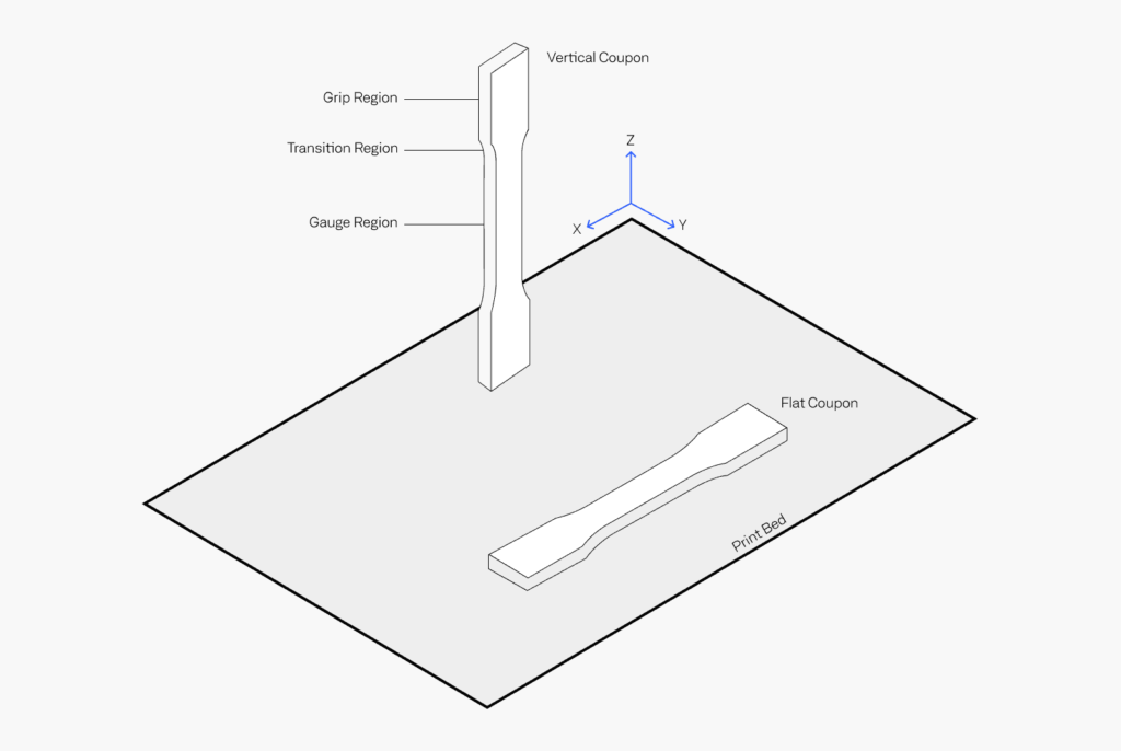
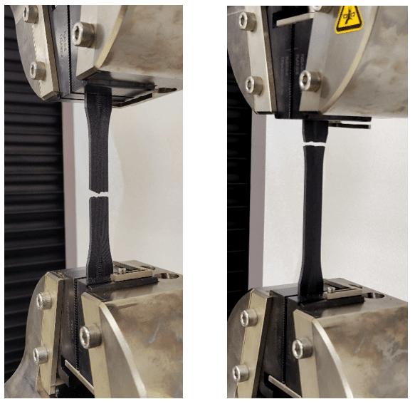
The tensile coupons consist of a grip, gauge, and transition region where the profile changes from wide to narrow. In the transition region, each consecutive layer is narrower than the previous which creates notches at the interlayers. These notches are sites for stress concentrations during testing and can result in premature failure of the material at the transition region. In addition, changes in the time-per-layer as the coupon’s profile narrows would influence the weld strength at different section of the coupon and provide a non-uniform thermal history. This results in failures in the non-gauge section of the coupons and inaccurate tensile results. According to the ASTM D638 standard, the coupons are only allowed to fail at the gauge section of the geometry for reliable strength results. The image below demonstrates an optimum failure versus a poor failure at the transition region.
The poor tensile failure of z-axis coupons coupled with the large scatter of strength results limits the use 3D printing for businesses, since there is a large uncertainty in part performance. AON3D, in collaboration with the National Research Council of Canada and Toronto Metropolitan University, has recently published a new method of evaluating z-direction properties by using interlayer shear testing instead of uniaxial tensile tests. This work is being extended with the goal to establish new AM specific test standards for 3D printed thermoplastics. The next section summarizes the interlayer shear testing method and its benefits over z-direction strength characterization.
Click here to view the full-length publication on the official ASTM website.
How does interlayer shear testing work?
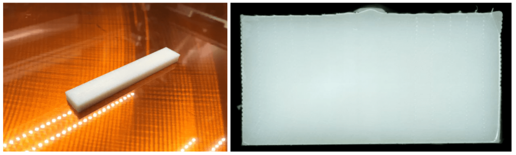
The proposed shear testing method is based on the ASTM D3846 Standard Test Method for In-Plane Shear Strength of Reinforced Plastics, which uses notched coupons that are loaded in compression. Blocks were printed out of ABS on the AON M2 using a set of optimized parameters. The M2 hardware was capable of producing dimensionally accurate parts with little to no visible voids when observed under a microscope.
Two sets of shear evaluation methods were developed to characterize the interlayer weld strength in the printed ABS. The first consisted of the ASTM D3846 coupons, which had notches cut and were loaded in compression to shear the printed layers apart. The second method used a highly modified version the ASTM standard with a smaller un-notched miniature block, which allowed for the direct measurement of strain and determination of shear modulus. The images below contain the respective test set-ups.
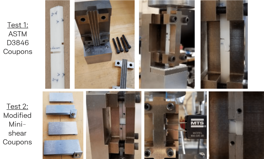
Both experiments provided a coefficient of variation between tested samples of 5% or less for strength, demonstrating the repeatability of this method over z-axis tensile testing. The notched D3846 coupons (Test 1) suffered from a moderate amount of interference from the test fixture. The mini-shear coupons (Test 2) did not exhibit this interference during testing and provided a more accurate assessment of shear strength with an average coefficient of variation across three batches of 2.2%.
Why in-plane shear is better for interlayer strength testing
Along with better experimental precision, the benefit of interlayer shear testing over z-axis tensile testing is that uniform shear stress can be applied over several beads and interlayers. Coupons printed vertically provide an assessment of the bulk behavior of printed parts which is specific to the coupon geometry and can not be extrapolated to predict the performance of different part geometries. On the other hand, shear testing can isolate the stress to a thin section of printed beads and the weakest plane, which is often the interlayer weld region, fails as expected. Therefore, in-plane shear testing provides a more accurate assessment of the interlayer mechanical strength. In addition, the printed blocks have a uniform cross section in the z-direction so that the temperature and time dependency of layer-by-layer welding can be studied more clearly. Our previous article on common issues in 3D printing goes into further detail on what causes poor layer weld strength. This in turn enables better traceability to process conditions and better predictability on part performance.

Achieve New Levels of Part Performance & Throughput
3D print the world's highest performance polymers - bigger, faster, and stronger than ever.